RHEL 6 Clustering
Cluster Software
| Name | Detail | Required |
|---|---|---|
| cman | Red Hat Cluster Manager | Yes |
| lvm2-cluster | Cluster extensions for userland logical volume management tools | Yes |
| rgmanager | Open Source HA Resource Group Failover for Red Hat Cluster | Yes |
| ricci | Remote Cluster and Storage Management System | Yes |
Cluster Services
| Detail | Service Name | Startup Order |
|---|---|---|
| Cluster Manager: Manages the following services qdiskd, fenced, dlm_controld and gfs_controld | cman | 1 |
| Cluster Logical Volume Manager | clvmd | 2 |
| Cluster Resource Manager | rgmanager | 3 |
| Cluster Management and Configuration Daemon | ricci | 4 |
Cluster Configuration Files
| Definition | File Location |
|---|---|
| Cluster configuration file | /etc/cluster/cluster.conf |
| Cluster resource scripts | /usr/share/cluster/ |
Cluster Log File Locations
| Detail | File Location |
|---|---|
| Resource Manager Log | /var/log/cluster/rgmanager.log |
| Fencing Log | /var/log/cluster/fenced.log |
| Quorum Disk Log | /var/log/cluster/qdiskd.log |
| GFS Log | /var/log/cluster/gfs_controld.log |
| DLM Log | /var/log/cluster/dlm_controld.log |
| Corosysnc Log | /var/log/cluster/corosync.log |
Check Cluster Status
| Detail | Command |
|---|---|
| Check cluster status | clustat |
| Check cluster status every x seconds | clustat -i [interval] |
| Check cluster status with extra detail | clustat -l |
| Check configured nodes and their votes | ccs_tool lsnode |
| Display cluster nodes | cman_tool |
Cluster Resource Group Administration
| Detail | Command |
|---|---|
| Restart Resource in place | clusvcadm -R [resource name] |
| Relocate Resource to another member | clusvcadm -r [resource name] -m [member name] |
| Disable Resource | clusvcadm -d [resource name] |
| Enable Resource | clusvcadm -e [resource name] |
| Freeze Resource | clusvcadm -Z [resource name] |
| Unfreeze Resource | clusvcadm -U [resource name] |
Testing Cluster Services
| Detail | Command |
|---|---|
| Status resource in test mode | rg_test test [cluster config] status service [resource-name] |
| Start resource in test mode | rg_test test [cluster config] start service [resource-name] |
| Stop resource in test mode | rg_test test [cluster config] stop service [resource-name] |
Cluster Infrastructure
The Red Hat Cluster Suite cluster infrastructure provides the basic functions for a group of computers (called nodes or members) to work together as a cluster. Once a cluster is formed using the cluster infrastructure, you can use other Red Hat Cluster Suite components to suit your clustering needs (for example, setting up a cluster for sharing files on a GFS file system or setting up service failover). The cluster infrastructure performs the following functions:
- Cluster management
- Lock management
- Fencing
- Cluster configuration management
Note The maximum number of nodes supported in a Red Hat Cluster is 16.
1.3.1. Cluster Management
Cluster management manages cluster quorum and cluster membership. CMAN (an abbreviation for cluster manager) performs cluster management in Red Hat Cluster Suite for Red Hat Enterprise Linux 5. CMAN is a distributed cluster manager and runs in each cluster node; cluster management is distributed across all nodes in the cluster (refer to Figure 1.2, “CMAN/DLM Overview”). CMAN keeps track of cluster quorum by monitoring the count of cluster nodes. If more than half the nodes are active, the cluster has quorum. If half the nodes (or fewer) are active, the cluster does not have quorum, and all cluster activity is stopped. Cluster quorum prevents the occurrence of a “split-brain” condition — a condition where two instances of the same cluster are running. A split-brain condition would allow each cluster instance to access cluster resources without knowledge of the other cluster instance, resulting in corrupted cluster integrity. Quorum is determined by communication of messages among cluster nodes via Ethernet. Optionally, quorum can be determined by a combination of communicating messages via Ethernet and through a quorum disk. For quorum via Ethernet, quorum consists of 50 percent of the node votes plus 1. For quorum via quorum disk, quorum consists of user-specified conditions.
Note By default, each node has one quorum vote. Optionally, you can configure each node to have more than one vote. CMAN keeps track of membership by monitoring messages from other cluster nodes. When cluster membership changes, the cluster manager notifies the other infrastructure components, which then take appropriate action. For example, if node A joins a cluster and mounts a GFS file system that nodes B and C have already mounted, then an additional journal and lock management is required for node A to use that GFS file system. If a cluster node does not transmit a message within a prescribed amount of time, the cluster manager removes the node from the cluster and communicates to other cluster infrastructure components that the node is not a member. Again, other cluster infrastructure components determine what actions to take upon notification that node is no longer a cluster member. For example, Fencing would fence the node that is no longer a member.
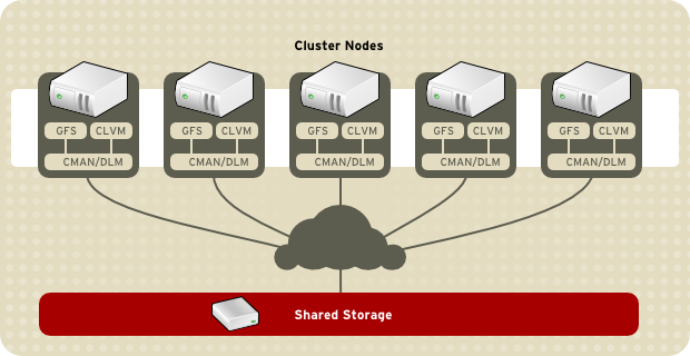
Figure 1.2. CMAN/DLM Overview
1.3.2. Lock Management
Lock management is a common cluster-infrastructure service that provides a mechanism for other cluster infrastructure components to synchronize their access to shared resources. In a Red Hat cluster, DLM (Distributed Lock Manager) is the lock manager. As implied in its name, DLM is a distributed lock manager and runs in each cluster node; lock management is distributed across all nodes in the cluster (refer to Figure 1.2, “CMAN/DLM Overview”). GFS and CLVM use locks from the lock manager. GFS uses locks from the lock manager to synchronize access to file system metadata (on shared storage). CLVM uses locks from the lock manager to synchronize updates to LVM volumes and volume groups (also on shared storage).
1.3.3. Fencing
Fencing is the disconnection of a node from the cluster’s shared storage. Fencing cuts off I/O from shared storage, thus ensuring data integrity. The cluster infrastructure performs fencing through the fence daemon, fenced. When CMAN determines that a node has failed, it communicates to other cluster-infrastructure components that the node has failed. fenced, when notified of the failure, fences the failed node. Other cluster-infrastructure components determine what actions to take — that is, they perform any recovery that needs to done. For example, DLM and GFS, when notified of a node failure, suspend activity until they detect that fenced has completed fencing the failed node. Upon confirmation that the failed node is fenced, DLM and GFS perform recovery. DLM releases locks of the failed node; GFS recovers the journal of the failed node. The fencing program determines from the cluster configuration file which fencing method to use. Two key elements in the cluster configuration file define a fencing method: fencing agent and fencing device. The fencing program makes a call to a fencing agent specified in the cluster configuration file. The fencing agent, in turn, fences the node via a fencing device. When fencing is complete, the fencing program notifies the cluster manager. Red Hat Cluster Suite provides a variety of fencing methods:
- Power fencing — A fencing method that uses a power controller to power off an inoperable node. Two types of power fencing are available: external and integrated. External power fencing powers off a node via a power controller (for example an API or a WTI power controller) that is external to the node. Integrated power fencing powers off a node via a power controller (for example,IBM Bladecenters, PAP, DRAC/MC, HP ILO, IPMI, or IBM RSAII) that is integrated with the node.
- SCSI3 Persistent Reservation Fencing — A fencing method that uses SCSI3 persistent reservations to disallow access to shared storage. When fencing a node with this fencing method, the node’s access to storage is revoked by removing its registrations from the shared storage.
- Fibre Channel switch fencing — A fencing method that disables the Fibre Channel port that connects storage to an inoperable node.
- GNBD fencing — A fencing method that disables an inoperable node’s access to a GNBD server.
Figure 1.3, “Power Fencing Example” shows an example of power fencing. In the example, the fencing program in node A causes the power controller to power off node D. Figure 1.4, “Fibre Channel Switch Fencing Example” shows an example of Fibre Channel switch fencing. In the example, the fencing program in node A causes the Fibre Channel switch to disable the port for node D, disconnecting node D from storage.
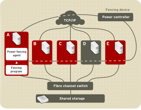
Figure 1.3. Power Fencing Example
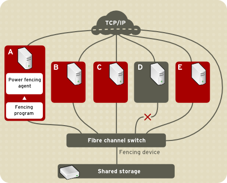
Figure 1.4. Fibre Channel Switch Fencing Example Specifying a fencing method consists of editing a cluster configuration file to assign a fencing-method name, the fencing agent, and the fencing device for each node in the cluster. The way in which a fencing method is specified depends on if a node has either dual power supplies or multiple paths to storage. If a node has dual power supplies, then the fencing method for the node must specify at least two fencing devices — one fencing device for each power supply (refer to Figure 1.5, “Fencing a Node with Dual Power Supplies”). Similarly, if a node has multiple paths to Fibre Channel storage, then the fencing method for the node must specify one fencing device for each path to Fibre Channel storage. For example, if a node has two paths to Fibre Channel storage, the fencing method should specify two fencing devices — one for each path to Fibre Channel storage (refer to Figure 1.6, “Fencing a Node with Dual Fibre Channel Connections”).

Figure 1.5. Fencing a Node with Dual Power Supplies
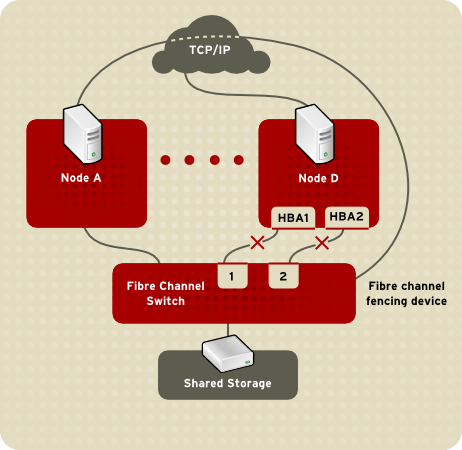
Figure 1.6. Fencing a Node with Dual Fibre Channel Connections You can configure a node with one fencing method or multiple fencing methods. When you configure a node for one fencing method, that is the only fencing method available for fencing that node. When you configure a node for multiple fencing methods, the fencing methods are cascaded from one fencing method to another according to the order of the fencing methods specified in the cluster configuration file. If a node fails, it is fenced using the first fencing method specified in the cluster configuration file for that node. If the first fencing method is not successful, the next fencing method specified for that node is used. If none of the fencing methods is successful, then fencing starts again with the first fencing method specified, and continues looping through the fencing methods in the order specified in the cluster configuration file until the node has been fenced.
1.3.4. Cluster Configuration System
The Cluster Configuration System (CCS) manages the cluster configuration and provides configuration information to other cluster components in a Red Hat cluster. CCS runs in each cluster node and makes sure that the cluster configuration file in each cluster node is up to date. For example, if a cluster system administrator updates the configuration file in Node A, CCS propagates the update from Node A to the other nodes in the cluster (refer to Figure 1.7, “CCS Overview”).
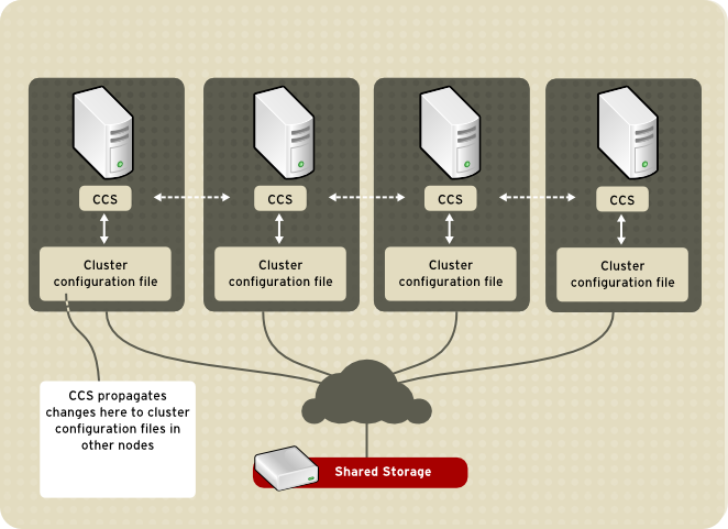
Figure 1.7. CCS Overview Other cluster components (for example, CMAN) access configuration information from the configuration file through CCS (refer to Figure 1.7, “CCS Overview”).
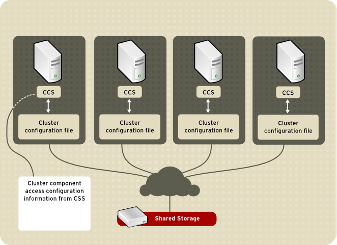
Figure 1.8. Accessing Configuration Information The cluster configuration file (/etc/cluster/cluster.conf) is an XML file that describes the following cluster characteristics:
- Cluster name — Displays the cluster name, cluster configuration file revision level, and basic fence timing properties used when a node joins a cluster or is fenced from the cluster.
- Cluster — Displays each node of the cluster, specifying node name, node ID, number of quorum votes, and fencing method for that node.
- Fence Device — Displays fence devices in the cluster. Parameters vary according to the type of fence device. For example for a power controller used as a fence device, the cluster configuration defines the name of the power controller, its IP address, login, and password.
- Managed Resources — Displays resources required to create cluster services. Managed resources includes the definition of failover domains, resources (for example an IP address), and services. Together the managed resources define cluster services and failover behavior of the cluster services.